Enhancing Humanoid Robot Mobility: Which Key Parameters of Motion Joints Need Control?
Humanoid robots, also known as anthropomorphic robots, are generally considered to be robots that should possess human-like appearance, perception, decision-making, behavior, and interaction capabilities. They can perform a series of tasks such as environmental perception, autonomous movement, and behavioral interaction in living and working scenarios, much like humans.
In recent years, major developed countries worldwide have strengthened the R&D and industrial layout of humanoid robots. The "Guiding Opinions on the Innovative Development of Humanoid Robots" issued by the Ministry of Industry and Information Technology (MIIT) of China mentions: Humanoid robots are expected to become disruptive products following computers, smartphones, and new energy vehicles, profoundly transforming human production and lifestyle, and reshaping the global industrial landscape.
According to relevant forecasts, the market size for humanoid robots in China is expected to reach 10.471 billion CNY by 2026, 75 billion CNY by 2029, and is projected to reach a scale of 300 billion CNY by 2035.
Compared to traditional industrial robots, humanoid robots require a very high number of Degrees of Freedom (DoF), and the number of articulated joints used is significantly increased. The manufacturing capability of these joint components has thus become key to enhancing robot mobility.

Image Source: Unitree Robotics G1
These joints include brushless DC servo motors, coreless motors, planetary gear reducers, harmonic drives, ball screws, etc. Overall, motors, reducers, and lead screws are the key components crucial for the movement of humanoid robots.
Therefore, in manufacturing, controlling the critical dimensions and parameters of these three major components is particularly important.
In this post, Dr. Atometrics will introduce this topic based on Atometrics's experience in assisting enterprises with controlling key parts.
Motors
In motor manufacturing, companies focus on the dimensions of the motor magnetic tiles, the dimensions of silicon steel laminations, and the dimensions of the rotor shaft.
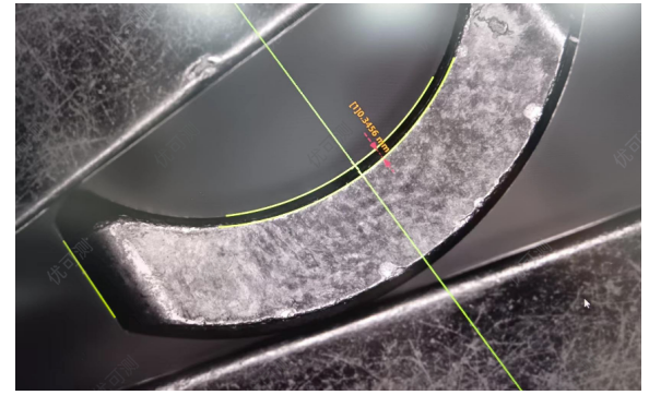
Magnetic Tile Dimension Measurement - Flash Measurement System FM Series
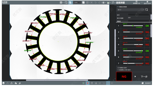
Silicon Steel Lamination Dimension Measurement - Flash Measurement System FM Series
Motor Bearing Dimension Measurement - Flash Measurement System FM Series
For brushed motors, companies also use microscopes for failure analysis of the carbon brushes.
For some precision motors, companies may even choose White Light Interferometers (WLI) to analyze the contact surface between the carbon brush and the commutator, controlling the surface roughness on both sides to reduce wear, lower noise, and extend carbon brush life.
Carbon Brush Wear Volume Measurement - White Light Interferometer AM Series
In AC motor manufacturing, companies also use high-magnification microscopes for failure analysis, surface defect analysis, etc., of the stator coil windings.
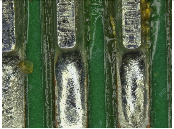
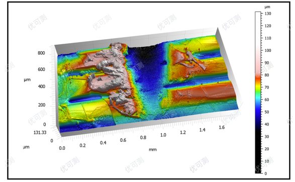
Motor Circuit Solder Joint Failure Analysis -Super Large Depth of Field Digital Microscope AH Series
Multiple precise coreless motors are deployed in dexterous hands. In their manufacturing, manufacturers also focus on the dimensions of the housing, permanent magnets, and Hall sensors. They procure equipment like Flash Measurement Systems for online sampling inspection or full inspection of these components' dimensions.
In servo motors, the "magnetic encoder", which controls the motor's rotation angle, is also a key focus for manufacturers. Some companies procure White Light Interferometers to control the laser groove height, surface roughness, and magnetic height of the encoder. For some high-precision encoders, surface roughness control must even reach the nanometer level.
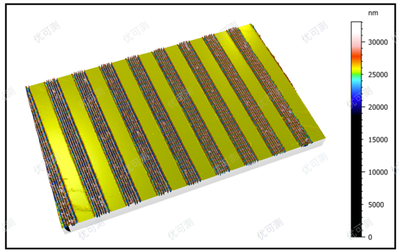
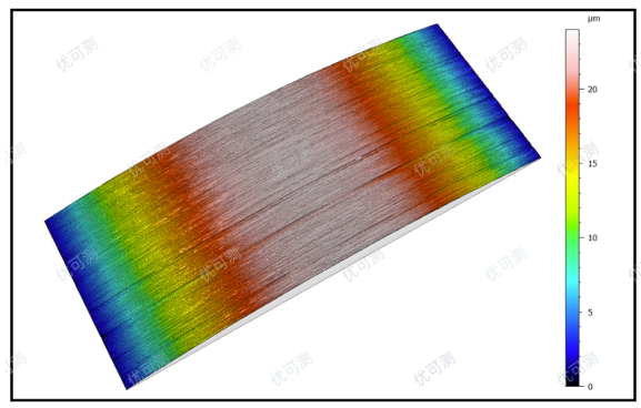
Magnetic Encoder Micro-topography Measurement - White Light Interferometer AM Series
Magnetic Encoder Roughness Measurement - White Light Interferometer AM Series
For some high-speed motors, manufacturers also focus on the shaft runout, using spectral chromatic sensors capable of detecting minute runout for measurement.
Reducers/Gearboxes
Many reducers are equipped with magnetic encoders or optical encoders. The dimensions and surface roughness of these encoders also need to be controlled.
In the motion joint modules composed of both reducers and motors, multiple gears are typically included, such as planetary gears and internal gears of the reducer. To reduce gear meshing resistance, decrease friction, and enhance the motion joint's lifespan, manufacturers control the dimensions of gears, shafts, and sleeves; the shaft runout of the transmission shaft; and the surface roughness of gear meshing surfaces. White Light Interferometers, Flash Measurement Systems, line laser sensors, and high-magnification Super Large Depth of Field Digital Microscope are common inspection equipment used in these control steps.
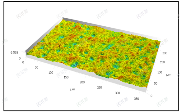
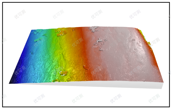
Planetary Gear Roughness Measurement - White Light Interferometer AM Series
Reducer Gear Wear Analysis - White Light Interferometer AM Series
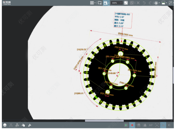
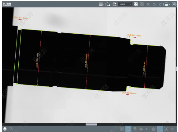
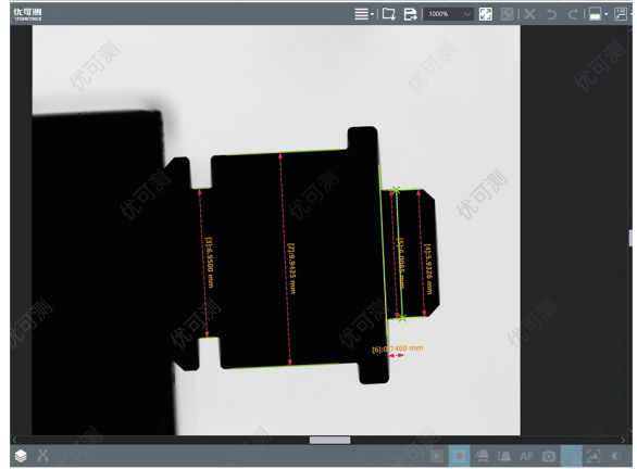
Reducer Gear Measurement - Flash Measurement System FM Series
Lead Screws
Currently, some humanoid robot motion joints utilize linear motion solutions such as ball screws. For example, Tesla's Optimus robot's hand includes 12 planetary ball screw structures, and the leg includes 14 planetary ball screws. To reduce motion noise and improve motion efficiency, planetary ball screw structures require precision grinding machines for processing, as well as high-precision White Light Interferometers and other measuring equipment for precise control of shaft and screw shaft runout, and the surface roughness of gear meshing surfaces.
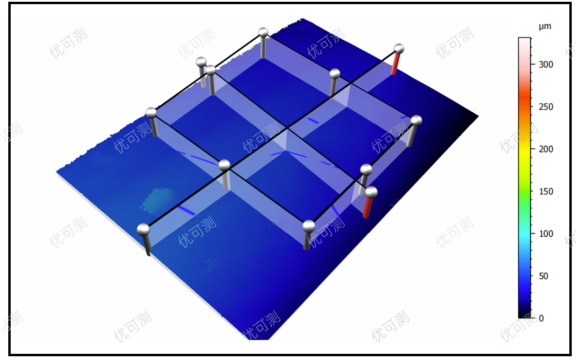
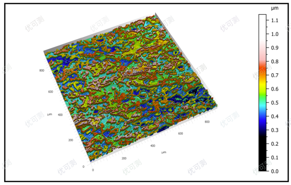
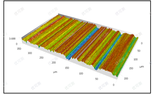
Ball Screw Wide Tooth Surface Roughness Measurement - White Light Interferometer AM Series
Lead Screw Thread Inclined Surface Topography Analysis - White Light Interferometer AM Series

Boardstone lntelligent(Shenzhen)Co.,Ltd.
6F Building C Kaifa Plaza,7006 Caitian Rd.,Futian Dist,Shenzhen
Hotline:400 080 3885
Sales@atometrics.com.cn
WhatsApp: +86 13316897904