In the field of industrial precision measurement, flatness measurement is a key indicator for evaluating the flatness of a surface. Depending on accuracy requirements, workpiece size, environmental conditions, budget, and application scenarios, various common methods and equipment are available:
I. Main Measurement Methods and Corresponding Equipment
1. Reference Plane Comparison Method
Principle: The surface under test is compared to a known high-precision reference plane (e.g., an optical flat, surface plate) by measuring the gap or interference fringes between them to determine the flatness deviation.
Common Equipment:
Optical Flat: Utilizes the principle of light wave interference. The flat is placed on the test surface, and monochromatic light creates interference fringes. The curvature and number of fringes directly reflect the flatness deviation. Accuracy can reach the nanometer level (λ/10 or higher, λ≈0.6μm).
Straightedge (Knife-edge/Parallel) + Feeler Gauge: A high-precision straightedge is placed on the test surface, and the maximum gap between the edge and the surface is measured with a feeler gauge. Suitable for quick inspection on the shop floor; relatively low accuracy (micron to tens of microns level).
Precision Surface Plate (Granite Plate) + Dial Indicator (Dial Gauge/Micrometer Indicator): The workpiece is placed on a precision surface plate. A dial indicator is mounted on a fixed stand, and the workpiece or the indicator stand is moved to measure height differences relative to the plate at various points on the surface. Flatness error is calculated through data processing (e.g., least squares method, minimum zone method). Accuracy depends on plate flatness, indicator accuracy, and measurement method (typically can reach several microns level).
2. Level Method
Principle: Utilizes gravity as a reference to measure the variation in inclination angle of points on the test surface relative to the horizontal plane. The angular differences are converted into height differences through calculation to obtain the flatness error.
Common Equipment:
Frame Level/Bar Level: Traditional mechanical levels. Relatively low accuracy (e.g., 0.02mm/m), cumbersome operation, complex data processing. Suitable for applications with low requirements or for leveling large equipment during installation.
Electronic Level: Core component is an electronic tilt sensor. The level is moved across the test surface in a defined step pattern and path, automatically recording the tilt angle at each point. Dedicated software calculates the flatness error (least squares plane, minimum zone method, etc.). High accuracy (can reach 1μm/m or even higher), high efficiency. Particularly suitable for flatness measurement and installation leveling of large workpieces (e.g., machine tool guides, platforms).
3. Coordinate Measurement Method
Principle: Precisely measures the spatial coordinates (X, Y, Z) of multiple points on the test surface in three-dimensional space. A reference plane is then fitted using mathematical methods (least squares method, minimum zone method, diagonal method), and the deviation of each measured point relative to this plane is calculated. The sum of the absolute values of the maximum positive and maximum negative deviations is the flatness error.
Common Equipment:
Coordinate Measuring Machine (CMM): One of the most versatile and powerful precision measuring instruments. Acquires surface point cloud data via contact probes (touch-trigger or scanning) or non-contact probes (laser, optical). High accuracy (can reach sub-micron level), capable of measuring multiple geometric tolerances simultaneously, high degree of automation. Suitable for small to medium-sized workpieces in laboratory or high-precision workshop environments.
Laser Tracker: Uses laser interferometry for distance measurement and angular encoders to determine the spatial position of a target (retroreflector). An operator moves the target over the test surface, and the instrument tracks and records point coordinates in real-time. Very large measurement range (tens of meters), high accuracy (micron to tens of microns level). Especially suitable for on-site measurement of extra-large workpieces (e.g., aircraft fuselages, wind turbine blade molds, large machine tool structural components).
Articulated Arm CMM: Portable coordinate measuring device. Consists of multiple rotary joints and rigid arms with built-in angular encoders. Measures point coordinates via a contact probe. Good portability, can be used on the shop floor, moderate measurement range (a few meters), accuracy typically in the tens of microns level.
4. Laser Interferometry Method
Principle: Utilizes the phenomenon of laser interference to directly measure height variations of the surface profile.
Common Equipment:
Laser Flatness Interferometer: Equipment specifically designed for measuring optical flats or high-precision mechanical flats. Generates a high-precision reference plane wavefront which interferes with the wavefront reflected from the test surface. Analyzing the interference pattern (fringe shape) allows direct, intuitive, and high-precision assessment of flatness. Accuracy can reach the nanometer level (λ/20 or higher). Primarily used in fields such as optical components, high-precision platforms, and semiconductor manufacturing.
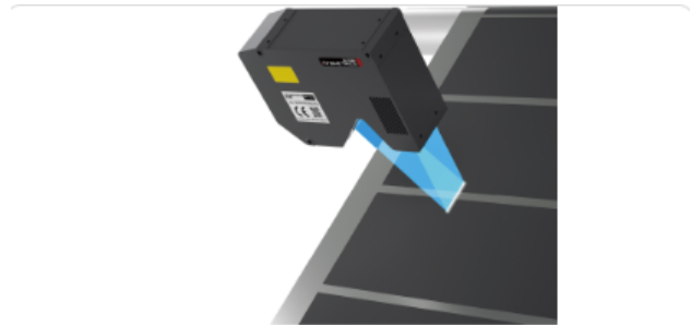
5. Optical Non-Contact Scanning Method
Principle: Uses optical principles (e.g., triangulation, confocal, white light interferometry, structured light) to rapidly acquire the three-dimensional topography (point cloud data) of the test surface without contact, then calculates flatness through software.
Common Equipment:
Laser Scanner/Line Laser Scanner: Based on laser triangulation principle, rapidly acquires dense point clouds.
White Light Interferometer/Phase-Shifting Interferometer: Uses light interference principles for nanometer-level accuracy measurement of micro-surface topography; also used for high-precision flatness measurement of small areas.
Structured Light Scanner: Projects specific patterns (e.g., fringes) onto the test surface and calculates 3D surface coordinates by capturing the deformed pattern with a camera.
Confocal Microscope: Utilizes the confocal principle for point-by-point or line-by-line scanning to obtain high-resolution, high-precision surface height information.
Characteristics: Fast speed, non-contact, acquires complete surface topography, wide accuracy range (sub-micron to tens of microns). Suitable for various materials (especially soft, easily scratched surfaces), complex surfaces, and applications requiring full-surface analysis.
6. Photogrammetry Method
Principle: Target points are placed on the test surface, photos are taken from multiple angles, and the 3D coordinates of the targets are calculated using computer vision algorithms to subsequently evaluate flatness. Often used for very large or hard-to-reach workpieces.
Common Equipment: Industrial close-range photogrammetry system (digital camera, coded targets, processing software).
II. Key Factors to Consider When Selecting Measurement Methods and Equipment
1. Accuracy Requirements: The primary consideration. Ranges from nanometer level (optical flat, laser interferometer, white light interferometer) to micron level (CMM, high-precision electronic level, laser tracker) to tens of microns or higher (frame level, straightedge with feeler gauge).
2. Workpiece Size:
Small size: Optical flat, CMM, white light interferometer, confocal microscope.
Medium size: CMM, electronic level, laser scanner.
Large/Extra-large size: Electronic level, laser tracker, photogrammetry, structured light scanner (depending on specific size).
3. Measurement Environment: Laboratory (high-precision equipment like CMM, interferometer) vs. Production shop floor (portable equipment like electronic level, laser tracker, articulated arm, portable scanner). Influences like vibration, temperature, and dust must be considered.
4. Measurement Efficiency: Full-surface scanning (optical scanners) is generally faster than point measurement (CMM touch-trigger, level point-by-point). Automated CMMs and scanners offer the highest efficiency.
5. Contact vs. Non-Contact: Contact methods (CMM probe, level) may scratch soft surfaces; Non-contact methods (optical) are suitable for easily deformed, soft, hot, or clean surfaces.
6. Cost: Significant differences in equipment acquisition cost, maintenance cost, and operator training cost.
7. Data Output and Analysis: Is complete point cloud data and 3D topography required, or just a flatness value? Data processing capabilities vary between devices.
8. Test Surface Characteristics: Material (reflectivity, transparency), roughness, color, etc., can affect the suitability of optical methods.
III. Summary
Highest Accuracy (Nanometer level): Optical flat, laser flatness interferometer, white light interferometer.
High Accuracy & General Purpose (Micron level): Coordinate Measuring Machine (CMM), high-precision electronic level, laser tracker.
Large Workpiece On-Site Measurement: Electronic level, laser tracker, photogrammetry.
Rapid Full-Surface Scanning: Various optical scanners (laser, structured light).
Quick & Simple Shop Floor Measurement: Straightedge + Feeler Gauge, Frame Level (lower accuracy).
Portable & Flexible: Articulated Arm CMM, portable optical scanner, electronic level.
In practical applications, it is often necessary to weigh the above factors according to specific needs to select the most suitable and cost-effective measurement method and equipment. CMMs, electronic levels, and various optical scanners are particularly widely used in modern industrial precision measurement.

Boardstone lntelligent(Shenzhen)Co.,Ltd.
6F Building C Kaifa Plaza,7006 Caitian Rd.,Futian Dist,Shenzhen
Hotline:400 080 3885
Sales@atometrics.com.cn
WhatsApp: +86 13316897904